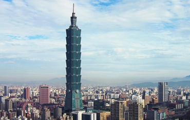
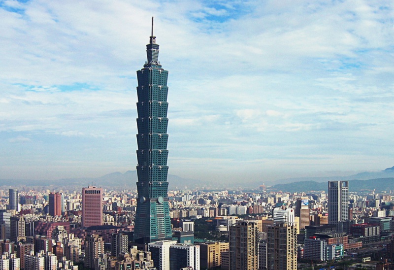
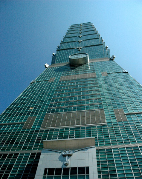
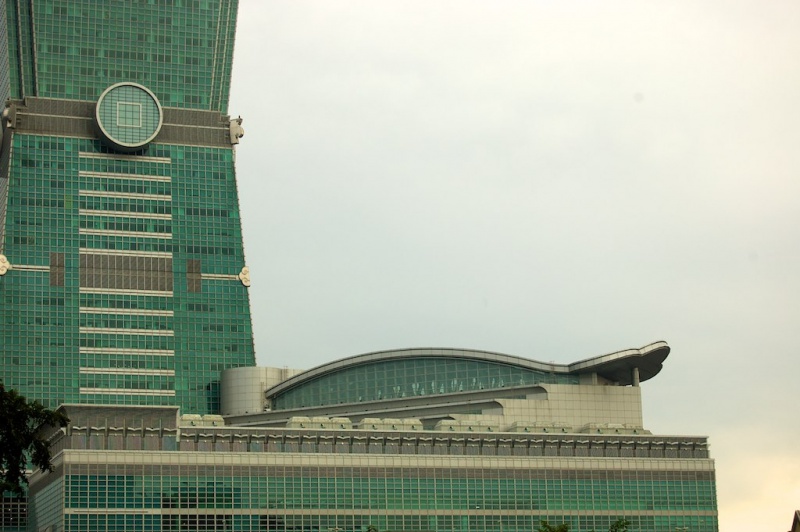
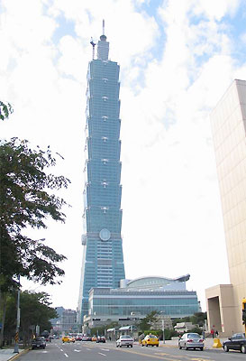
Taipei 101
Gravity Systems
 The tower superstructure is a steel frame with H shape steel beams acting composite with the floor slab through shear studs, and floor concrete acting composite with metal deck.
Gravity load is carried vertically by a variety of columns. Within the core, sixteen columns are located at the crossing points of four lines of bracing in each direction. The columns are boxes of steel plate, filled with concrete for added stiffness at lower levels.
On the perimeter, up to the 26th floor, each of the four building faces has two ‘super-columns,’ two ‘sub-super-columns,’ and two corner columns. The ‘super-columns’ and ‘sub-super-columns’ are steel boxes, filled with 10,000psi concrete on lower floors for stiffness up to 62nd floor. Their width (measured parallel to the façade) is limited, to work with façade panel widths established as a standard on this project. Their depth (into the floor space) varies. It is minimized on upper floors, but is permitted to increase as the floor plan grows at lower floors, to enhance overturning stiffness without impacting floor layout flexibility.
Each face of the perimeter above the 26th floor has the two ‘super-columns’ continue upward. The balance of perimeter framing is a sloping Special Moment Resisting Frame (SMRF), a rigidly-connected grid of deep, stiff beams and columns which follows the tower’s exterior wall slope down each 8 story module. At each setback level, gravity load is transferred to ‘super-columns’ through a story-high diagonalized truss in the plane of the SMRF.
The topmost section of the building above 91st floor is much smaller in plan. Its loadings transfer to the core columns directly.
Lateral (Wind and Seismic) Systems
Lateral forces will be resisted through a combination of braced frames in the core, outriggers from core to perimeter, ‘super-columns’ and moment resisting frames in the perimeter and other selected locations.
By relative stiffness, the core bracing and outriggers carry most of the wind force and seismic force. Tower lateral systems are sized to limit tower story drift under the 50 years design wind load to an inter-story drift of h/200. Because of the severe wind load condition, stress requirements based on 100 years design wind load appear to govern the sizes of most lateral system bracing components, including the designs of some core and perimeter columns.
Within the core, bays between core columns are stiffened by diagonal braces. On outer faces, middle bays have ‘chevron’ braces (inverted Vs) through which the elevator lobby entrance passes. Side bays have single diagonals, eccentric only where required to clear minimum doorway requirements. On inner faces, middle bays are non-braced (special moment frames are provided) at office floors, to keep elevator lobbies open and spacious. Side bays have diagonal braces.
For additional core stiffness, the lowest floors from basement to 8th floor have concrete shear walls cast between core columns in addition to diagonal braces. From core to perimeter, outrigger trusses occur at 11 locations in elevation. Outriggers at 6 locations are one story high, fitting in mechanical floors. The other 5 locations are double-height, working with architectural requirements. In plan, 16 outriggers occur on each such floor.
For the dual seismic system, an independent Special Moment Resisting Frame (SMRF) is provided on each building face. From basement to the 26th floor, the SMRF consists of ductile steel beams framing between ‘strong’ columns – the exterior super-columns, exterior sub-super columns, and corner columns. Above 26th Floor, only two exterior super columns continue to rise up to 91st floor, so the SMRF consists of 600mm deep steel wide flange beams and columns, with columns sized to be significantly stronger than beams for stability in the event of beam yielding. Each 7-story of SMRF is carried by a story high truss to transfer gravity and outrigger forces to the super-columns, and to handle the greater story stiffness of the core at outrigger floors.
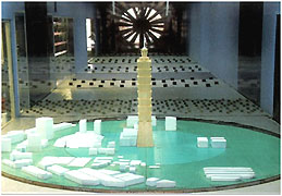
Damping System:
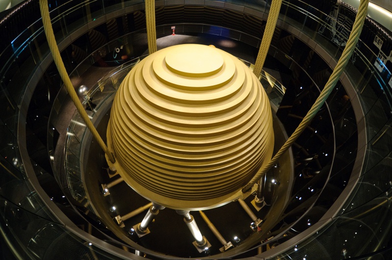
In an effort to reduce building lateral accelerations and to satisfy the vibration and comfort level requirement for the tower, a TMD system (Tuned Mass Damper) is designed and installed at the top of the building. The TMD system is to employ a mass consisted of built-up steel plates, suspended by cables as simple pendulum from the 92nd floor to give the Damper appropriate natural period of vibration. This simple passive system (TMD) is more reliable, requires minimum maintenance and is usually more economical, than an active TMD system.
Detailed Description of Foundation
Subsurface support for the tower consists of a concrete pile-supported mat foundation. In the tower area, piles are bored and cast in place, 1500mm in diameter with 20~30m sockets into weathered bedrock (allowable pile capacity 1100~1450 tons/pile).
The mat, based on f’c=6ksi (42Mpa) concrete strength (ACI cylinder test basis) is generally approximately 3.5m thick, with thickness variations due to local loadings. For example, the perimeter super-columns deliver larger gravity loads than other columns, and when overturning forces from wind and seismic load are added the total is much larger. Therefore, local zones, pads of mat is 4.7m thick in the region around super-columns.
Lateral forces will be resisted by a combination of soil friction, side bearing of piles against soil and edge bearing of the mat against the perimeter slurry wall and then to surrounding soils.
Milestones
1997.07 Development right acquired through public tender
1998.01 Ground breaking
1999.07 Construction Started
2000.06 Tower Column Erection Ceremony
2001.06 Top-Out Ceremony of Podium
2002.11 Podium Construction Completed
2003.07 Top-Out Ceremony of Tower
2003.10 Tower-Top Jacking Erection Completed
2003.11 Shopping Mall Opened
2004.12 Office Tower Opened
The tower superstructure is a steel frame with H shape steel beams acting composite with the floor slab through shear studs, and floor concrete acting composite with metal deck.Gravity load is carried vertically by a variety of columns. Within the core, sixteen columns are located at the crossing points of four lines of bracing in each direction. The columns are boxes of steel plate, filled with concrete for added stiffness at lower levels.
On the perimeter, up to the 26th floor, each of the four building faces has two ‘super-columns,’ two ‘sub-super-columns,’ and two corner columns. The ‘super-columns’ and ‘sub-super-columns’ are steel boxes, filled with 10,000psi concrete on lower floors for stiffness up to 62nd floor. Their width (measured parallel to the façade) is limited, to work with façade panel widths established as a standard on this project. Their depth (into the floor space) varies. It is minimized on upper floors, but is permitted to increase as the floor plan grows at lower floors, to enhance overturning stiffness without impacting floor layout flexibility.
Each face of the perimeter above the 26th floor has the two ‘super-columns’ continue upward. The balance of perimeter framing is a sloping Special Moment Resisting Frame (SMRF), a rigidly-connected grid of deep, stiff beams and columns which follows the tower’s exterior wall slope down each 8 story module. At each setback level, gravity load is transferred to ‘super-columns’ through a story-high diagonalized truss in the plane of the SMRF.
The topmost section of the building above 91st floor is much smaller in plan. Its loadings transfer to the core columns directly.
Lateral (Wind and Seismic) Systems
Lateral forces will be resisted through a combination of braced frames in the core, outriggers from core to perimeter, ‘super-columns’ and moment resisting frames in the perimeter and other selected locations.
By relative stiffness, the core bracing and outriggers carry most of the wind force and seismic force. Tower lateral systems are sized to limit tower story drift under the 50 years design wind load to an inter-story drift of h/200. Because of the severe wind load condition, stress requirements based on 100 years design wind load appear to govern the sizes of most lateral system bracing components, including the designs of some core and perimeter columns.
Within the core, bays between core columns are stiffened by diagonal braces. On outer faces, middle bays have ‘chevron’ braces (inverted Vs) through which the elevator lobby entrance passes. Side bays have single diagonals, eccentric only where required to clear minimum doorway requirements. On inner faces, middle bays are non-braced (special moment frames are provided) at office floors, to keep elevator lobbies open and spacious. Side bays have diagonal braces.
For additional core stiffness, the lowest floors from basement to 8th floor have concrete shear walls cast between core columns in addition to diagonal braces. From core to perimeter, outrigger trusses occur at 11 locations in elevation. Outriggers at 6 locations are one story high, fitting in mechanical floors. The other 5 locations are double-height, working with architectural requirements. In plan, 16 outriggers occur on each such floor.
For the dual seismic system, an independent Special Moment Resisting Frame (SMRF) is provided on each building face. From basement to the 26th floor, the SMRF consists of ductile steel beams framing between ‘strong’ columns – the exterior super-columns, exterior sub-super columns, and corner columns. Above 26th Floor, only two exterior super columns continue to rise up to 91st floor, so the SMRF consists of 600mm deep steel wide flange beams and columns, with columns sized to be significantly stronger than beams for stability in the event of beam yielding. Each 7-story of SMRF is carried by a story high truss to transfer gravity and outrigger forces to the super-columns, and to handle the greater story stiffness of the core at outrigger floors.
Damping System:
In an effort to reduce building lateral accelerations and to satisfy the vibration and comfort level requirement for the tower, a TMD system (Tuned Mass Damper) is designed and installed at the top of the building. The TMD system is to employ a mass consisted of built-up steel plates, suspended by cables as simple pendulum from the 92nd floor to give the Damper appropriate natural period of vibration. This simple passive system (TMD) is more reliable, requires minimum maintenance and is usually more economical, than an active TMD system.
Detailed Description of Foundation
Subsurface support for the tower consists of a concrete pile-supported mat foundation. In the tower area, piles are bored and cast in place, 1500mm in diameter with 20~30m sockets into weathered bedrock (allowable pile capacity 1100~1450 tons/pile).
The mat, based on f’c=6ksi (42Mpa) concrete strength (ACI cylinder test basis) is generally approximately 3.5m thick, with thickness variations due to local loadings. For example, the perimeter super-columns deliver larger gravity loads than other columns, and when overturning forces from wind and seismic load are added the total is much larger. Therefore, local zones, pads of mat is 4.7m thick in the region around super-columns.
Lateral forces will be resisted by a combination of soil friction, side bearing of piles against soil and edge bearing of the mat against the perimeter slurry wall and then to surrounding soils.
Milestones
1997.07 Development right acquired through public tender
1998.01 Ground breaking
1999.07 Construction Started
2000.06 Tower Column Erection Ceremony
2001.06 Top-Out Ceremony of Podium
2002.11 Podium Construction Completed
2003.07 Top-Out Ceremony of Tower
2003.10 Tower-Top Jacking Erection Completed
2003.11 Shopping Mall Opened
2004.12 Office Tower Opened